330130-075-11-05 Bently Nevada extension cable
Description
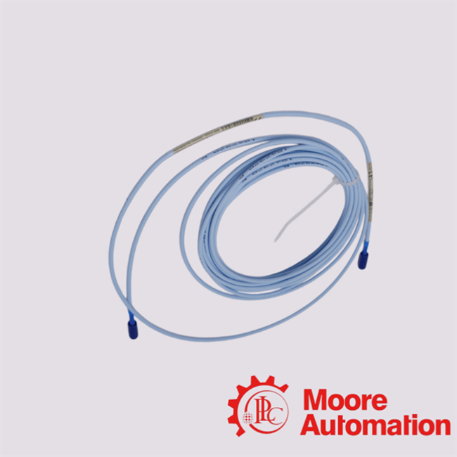
The 330130-075-11-05 is a 7.5-meter (24.6 ft) standard extension cable used to electrically connect the 3300 XL proximity probe to the Proximitor® sensor in the Bently Nevada 3300 monitoring architecture.It belongs to the 3300 XL machinery condition monitoring family, which is widely used in industrial asset protection systems for precise measurement of shaft vibration, axial displacement, and position in fluid-film bearing machines.
Testing Procedure of 330130-075-11-05 Extension Cable
1️⃣ Visual and Mechanical Inspection
The initial step focuses on physical condition assessment:
- Inspect cable jacket for cuts, abrasions, deformation, or extrusion damage
- Verify connector integrity (no bent pins, corrosion, or contamination)
- Confirm correct part number marking: 330130-075-11-05
- Check shielding termination and grounding structure
Objective: Eliminate mechanical defects that may affect high-frequency signal transmission.
|
2️⃣ Continuity Test
Electrical continuity is verified using a multimeter or cable tester:
- Confirm end-to-end continuity of the center conductor
- Verify continuity of the shielding conductor
- Ensure absence of open circuits
- Ensure no unintended short circuits between conductor and shield
Acceptance criterion: Near-zero resistance for conductors; no leakage paths.
|
3️⃣ Insulation Resistance Test
A megohmmeter is used to evaluate dielectric integrity:
- Apply DC test voltage (typically 250–500 V)
- Measure resistance between center conductor and shield
Acceptance criterion: High insulation resistance (typically in MΩ to GΩ range), indicating no leakage or insulation breakdown.
|
4️⃣ Capacitance and Impedance Verification
This step ensures system-level compatibility with the 3300 XL proximity system:
- Measure cable capacitance (pF/m)
- Verify nominal system impedance (75 Ω design architecture)
- Evaluate signal attenuation consistency
Objective: Maintain calibration integrity between probe, extension cable, and Proximitor sensor.
|
5️⃣ EMI and Shielding Effectiveness Test
Electromagnetic compatibility is evaluated under simulated industrial interference:
- Inject controlled electromagnetic noise (EMI stress conditions)
- Observe noise coupling into signal path
- Evaluate shielding effectiveness performance
Acceptance criterion: No significant signal distortion or noise-induced drift.
|
Advanced Engineering FAQ
Q1: What electro-mechanical interface architecture is defined for the 330130-075-11-05 in its official datasheet, and how does it govern mating compatibility and system interoperability?
A1:
The datasheet for 330130-075-11-05 typically specifies the electro-mechanical interface geometry, including mating envelope, contact alignment scheme, and polarization constraints. These parameters collectively ensure deterministic mating behavior, prevent misalignment during blind mating operations, and maintain interoperability within standardized connector ecosystems.
Q2: How does the 330130-075-11-05 characterize its current-carrying capacity and what thermal-rise constraints are imposed under steady-state operation according to its datasheet?
A2:
For 330130-075-11-05, the datasheet generally defines rated current per contact along with permissible temperature rise under nominal loading conditions. These constraints are derived from contact resistance, conductor cross-section, and thermal dissipation characteristics, ensuring compliance with safe-operating-area (SOA) requirements.
Q3: What dielectric performance thresholds and insulation resistance metrics are specified for the 330130-075-11-05 in high-voltage or high-humidity environments?
A3:
The 330130-075-11-05 datasheet typically outlines dielectric withstand voltage and insulation resistance values, which quantify the connector’s ability to resist breakdown and leakage currents. These parameters are critical in assessing suitability for high-humidity, pollution degree, or transient overvoltage conditions.
Q4: Which material science and metallurgical compositions are employed in the 330130-075-11-05, and how do they influence conductivity, wear resistance, and long-term reliability?
A4:
According to its datasheet framework, 330130-075-11-05 materials often include high-conductivity copper alloys for contacts and engineered thermoplastics or high-temperature polymers for housings. Surface plating systems (e.g., selective gold or tin plating) are used to optimize fretting corrosion resistance and reduce insertion loss over lifecycle cycles.
Q5: What mechanical endurance specifications—such as mating cycle life and insertion/extraction force profiles—are defined for the 330130-075-11-05?
A5:
The datasheet of 330130-075-11-05 typically defines mating durability in terms of cycle life rating and force-displacement characteristics. These parameters ensure predictable mechanical degradation behavior, quantify contact wear accumulation, and validate usability in repetitive assembly/disassembly environments.
Inquiry now: miya@mvme.cn
Bently Nevada Hot Series:
3300 XL Proximity Probe
3300 Proximitor Sensor
3500 Power Supply
1900/65A
3500/42 Monitor Module
The 990 Vibration Transmitter

You May Need
| 3300/50-02-01-00-00 |
2201/03-01 |
1800/20-XX-90-02-00 MOD 158611-01 |
| 3300/50 |
21747-080-00 |
177230-02-01-05 |
| 3300/47 |
21505-00-12-05-02 |
177230-01-02-05 |
| 3300/45 |
200350-02-00-CN |
177230-01-01-05 |
| 3300/35 |
190501-04-00-00 |
170180-01-05 |
| 3300/20 |
1900/65A 172323-01/1900/65A 167699-02 |
16925-15 |
| 3300/16 |
1900/65A 172323-01 1900/65A 167699-02 |
16710-20 |
| 30190-035-00-00 |
1900/65 |
16710-14 |
| 2300/20-02 |
1900/55 |
16710-10 |
| 2300/20-00 |
18622-030-01 |
16710-06 |
Ready to elevate your automation system? Contact us today for more information or to make a purchase:
What’s app:86-18020776792
Skpye:miyazheng520
miya@mvme.cn (click) || 86-18020776792

 Your message must be between 20-3,000 characters!